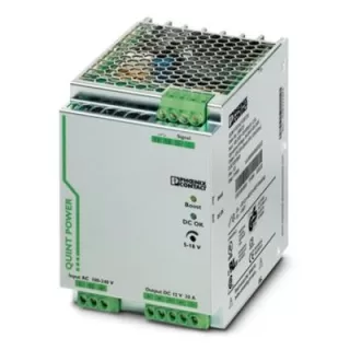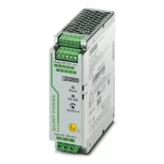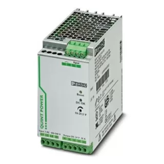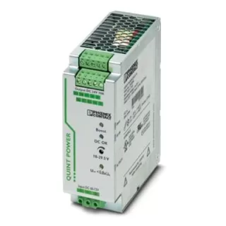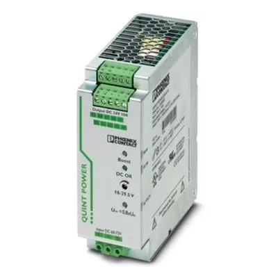
Phoenix Contact QUINT-PS/60-72DC/24DC/10/CO QUINT-PS/60-72DC/24DC/10/CO DC/DC Converter, with Protective Coating
- Brand
- Phoenix Contact
- Model number
- QUINT-PS/60-72DC/24DC/10/CO
- Category
- DIN-Rail Power Supplies
Primary-switched QUINT DC/DC converter with wide range input for DIN rail mounting with SFB (Selective Fuse Breaking) technology, input: 60-72 V DC, output 24 V DC / 10 A
Price and availability on request
We reply by email or phone, Monday to Saturday, 10:30 am to 6:30 pm.
Several models? Add each to your enquiry list and send them as one enquiry.
Key features
- Output 24 V DC ±1 %, 10 A (-40 °C ... 60 °C)
- Input 60 V DC ... 72 V DC
- Efficiency > 91 % (UIN 60 V DC / UOUT 24 V DC)
- Width 48 mm
- Operating temperature -25 °C ... 70 °C (> 60 °C Derating - 2,5 %/K)
- Degree of protection IP20
Specifications
| Nominal input voltage range | 60 V DC ... 72 V DC |
|---|---|
| Input voltage range | 42 V DC ... 96 V DC |
| Wide-range input | yes |
| Input voltage range DC | 42 V DC ... 96 V DC |
| Voltage type of supply voltage | DC |
| Inrush current | < 9 A (typical) |
| Inrush current integral (I2t) | 0.64 A2s |
| Mains buffering time | typ. 10 ms (60 V DC) |
| Current consumption | 5.6 A (60 V DC); 4.7 A (72 V DC) |
| Reverse polarity protection | , ≤ 30 V DC |
| Nominal power consumption | 268 VA |
| Protective circuit | Transient surge protection; Varistor |
| Input fuse | 10 A 150 V DC (internal (device protection)) |
| Efficiency | > 91 % (UIN 60 V DC / UOUT 24 V DC); > 91 % (UIN 72 V DC / UOUT 24 V DC) |
|---|---|
| Output characteristic | U/I |
| Nominal output voltage | 24 V DC ±1 % |
| Setting range of the output voltage (USet) | 18 V DC ... 29.5 V DC (> 24 V DC, constant capacity restricted) |
| Nominal output current (IN) | 10 A (-40 °C ... 60 °C) |
| POWER BOOST (IBoost) | 12.5 A (-40 °C ... 40 °C permanent, UOUT = 24 V DC) |
| Selective Fuse Breaking (ISFB) | 60 A (12 ms) |
| Magnetic circuit breaker tripping | B2 / B4 / B6 |
| Derating | 60 °C ... 70 °C (2.5 %/K) |
| Feedback voltage resistance | 35 V DC |
| Protection against overvoltage at the output (OVP) | < 35 V DC |
| Max. capacitive load | unlimited |
| Active current limitation | 18 A |
| Control deviation | < 1 % (change in load, static 10 % ... 90 %); < 2 % (change in load, dynamic 10 % ... 90 %); < 0.1 % (change in input voltage ±10 %) |
| Residual ripple | < 20 mVPP |
| Short-circuit-proof | yes |
| Output power | 240 W |
| Peak switching voltages nominal load | < 10 mVPP (20 MHz) |
| Maximum no-load power dissipation | 4 W (UIN 60 V DC) |
| Power loss nominal load max. | 24 W (UIN 60 V DC) |
| Rise time | < 2 ms (UOUT (10 % ... 90 %)) |
| Connection in parallel | yes, for redundancy and increased capacity |
| Connection in series | yes |
| Fuse protection (secondary side) | electronic; thermal-magnetic; thermal |
| Output description | UOUT > 0.9 x UN - High signal |
|---|---|
| Switching voltage range | 18 V DC ... 24 V DC |
| Maximum inrush current | < 20 mA (short-circuit-proof) |
| Output description | IOUT < IN - High signal |
|---|---|
| Switching voltage range | 18 V DC ... 24 V DC |
| Maximum inrush current | < 20 mA (short-circuit-proof) |
| Output description | UIN > 19.2 V - High signal |
|---|---|
| Switching voltage range | 18 V DC ... 24 V DC |
| Maximum inrush current | ≤ 20 mA (short-circuit-proof) |
| Output description | Relay |
|---|---|
| Output voltage | ≤ 30 V AC/DC |
| Maximum inrush current | ≤ 100 mA |
| Connection method | Screw connection |
|---|---|
| Conductor cross-section, rigid min. | 0.2 mm² |
| Conductor cross-section, rigid max. | 2.5 mm² |
| Conductor cross-section flexible min. | 0.2 mm² |
| Conductor cross-section flexible max. | 2.5 mm² |
| Conductor cross-section AWG min. | 24 |
| Conductor cross-section AWG max. | 12 |
| Stripping length | 8 mm |
| Screw thread | M3 |
| Tightening torque, min | 0.5 Nm |
| Tightening torque max | 0.6 Nm |
| Connection method | Screw connection |
|---|---|
| Conductor cross-section, rigid min. | 0.2 mm² |
| Conductor cross-section, rigid max. | 2.5 mm² |
| Conductor cross-section flexible min. | 0.2 mm² |
| Conductor cross-section flexible max. | 2.5 mm² |
| Conductor cross-section AWG min. | 24 |
| Conductor cross-section AWG max. | 12 |
| Stripping length | 7 mm |
| Screw thread | M3 |
| Tightening torque, min | 0.5 Nm |
| Tightening torque max | 0.6 Nm |
| Conductor cross-section, rigid min. | 0.2 mm² |
|---|---|
| Conductor cross-section, rigid max. | 2.5 mm² |
| Conductor cross-section flexible min. | 0.2 mm² |
| Conductor cross-section flexible max. | 2.5 mm² |
| Conductor cross-section AWG min. | 24 |
| Conductor cross-section AWG max. | 12 |
| Screw thread | M3 |
| Tightening torque, min | 0.5 Nm |
| Tightening torque max | 0.6 Nm |
| Types of signaling | LED; Active switching output; Relay contact |
|---|
| Status display | "DC OK" LED green |
|---|---|
| Color | green |
| Status display | "BOOST" LED yellow/IOUT > IN - LED on |
|---|---|
| Color | yellow |
| Note on status display | LED on |
| Status display | LED "UIN < 0.8 x UN V" yellow/UIN < 0.8 x UN V DC - LED on |
|---|---|
| Color | yellow |
| Note on status display | LED on |
| Note on status display | UOUT > 0.9 x UN - Contact closed |
|---|
| Number of phases | 1 |
|---|---|
| Insulation voltage input/output | 1.5 kV (type test); 1 kV (routine test); 1 kV (type test) |
| Product type | DC/DC converters |
|---|---|
| Product family | QUINT POWER |
| MTBF (IEC 61709, SN 29500) | > 1349000 h (25 °C); > 765000 h (40 °C) |
| Protection class | I |
|---|---|
| Degree of pollution | 2 |
| Width | 48 mm |
|---|---|
| Height | 130 mm |
| Depth | 125 mm |
| Installation distance right/left | 0 mm / 0 mm (≤ 70 °C) |
|---|---|
| Installation distance right/left (active) | 15 mm / 15 mm (≤ 70 °C) |
| Installation distance top/bottom | 50 mm / 50 mm (≤ 70 °C) |
| Installation distance top/bottom (active) | 50 mm / 50 mm (≤ 70 °C) |
| Width | 122 mm |
|---|---|
| Height | 130 mm |
| Depth | 51 mm |
| Mounting type | DIN rail - 35 mm |
|---|---|
| Assembly note | alignable - PN ≥50%, 5 mm horizontally, 15 mm next to active components, 50 mm verticallyalignable - PN <50%, 0 mm horizontally, 40 mm vertically top, 20 mm vertically bottom |
| Mounting position | horizontal DIN rail NS 35, EN 60715 |
| With protective coating | yes |
| Housing material | Metal |
|---|---|
| Type of housing | Aluminum (AlMg3) |
| Hood version | Galvanized sheet steel, free from chrome (VI) |
| Degree of protection | IP20 |
|---|---|
| Ambient temperature (operation) | -25 °C ... 70 °C (> 60 °C Derating - 2,5 %/K) |
| Ambient temperature (storage/transport) | -40 °C ... 85 °C |
| Ambient temperature (start-up type tested) | -40 °C |
| Climatic class | 3K3 (in acc. with EN 60721) |
| Max. permissible relative humidity (operation) | 100 % (at 25 °C, non-condensing) |
| Shock | 18 ms, 30g, in each space direction (according to IEC 60068-2-27) |
| Vibration (operation) | < 15 Hz, amplitude ±2.5 mm (according to IEC 60068-2-6); 15 Hz ... 150 Hz, 2.3g, 90 min. |
| Temp code | T4 (-25 ... +70 °C; > 60 °C, Derating - 2,5 %/K) |
| Rail applications | EN 50121-4; EN 50155 |
|---|---|
| Standard – Electronic equipment for use in electrical power installations and their assembly into electrical power installations | EN 50178/VDE 0160 (PELV) |
| Standard - Electrical safety | EN 60950-1/VDE 0805 (SELV) |
| Standard – Safety extra-low voltage | EN 60950-1 (SELV); EN 60204 (PELV) |
| Standard - Safe isolation | DIN VDE 0100-410 |
| Noxious gas test | ISA-S71.04-1985 G3 Harsh Group A |
| Standard designation | Fire protection in rail vehicles |
|---|---|
| Standards/specifications | EN 45545-2 (HL3) |
| UL approvals | UL/C-UL listed UL 508; UL/C-UL Recognized UL 60950-1; UL ANSI/ISA-12.12.01 Class I, Division 2, Groups A, B, C, D T4 (Hazardous Location) |
|---|
Specifications are from the manufacturer's published information. Confirm critical values with us or the datasheet before ordering. Brand names, logos and model names are trademarks of their respective owners, used only to identify the product. Details
Model numbers in this series (1)
Send us the complete code you need and we will quote it.
2905011
About the QUINT-PS/60-72DC/24DC/10/CO
QUINT POWER power supply for DIN-rail mounting with maximum functionality. Primary-switched QUINT DC/DC converter with wide range input for DIN rail mounting with SFB (Selective Fuse Breaking) technology, input: 60-72 V DC, output 24 V DC / 10 A Order no. 2905011.
Related products
-
Phoenix Contact QUINT-PS/1AC/12DC/20 QUINT-PS/1AC/12DC/20 Power Supply
Please use the following item for new projects: 2904608 QUINT4-PS/1AC/12DC/15. Primary-switched power supply unit QUINT POWER, Screw connection, SFB Technology (Selective Fuse Breaking), input: 1-phase, output: 12 V DC / 20 A, adjustable from 5 V…
-
Phoenix Contact QUINT-PS/1AC/24DC/5/CO QUINT-PS/1AC/24DC/5/CO Power Supply, with Protective Coating
Please use the following item for new projects: 2904616 QUINT4-PS/1AC/24DC/10/+. Primary-switched power supply unit QUINT POWER, Screw connection, DIN rail mounting, SFB Technology (Selective Fuse Breaking), input: 1-phase, output: 24 V DC / 5 A…
-
Phoenix Contact QUINT-PS/3AC/24DC/20/CO QUINT-PS/3AC/24DC/20/CO Power Supply, with Protective Coating
Please use the following item for new projects: 1343940 QUINT4-PS/3AC/24DC/20/CO. Primary-switched power supply unit QUINT POWER, Screw connection, SFB Technology (Selective Fuse Breaking), input: 3-phase, output: 24 V DC / 20 A, adjustable from 18…
-
Phoenix Contact QUINT-PS/60-72DC/24DC/10 QUINT-PS/60-72DC/24DC/10 DC/DC Converter
Primary-switched QUINT DC/DC converter with wide range input for DIN rail mounting with SFB (Selective Fuse Breaking) technology, input: 60-72 V DC, output 24 V DC / 10 A