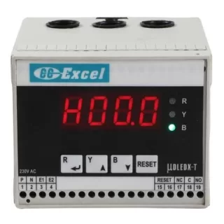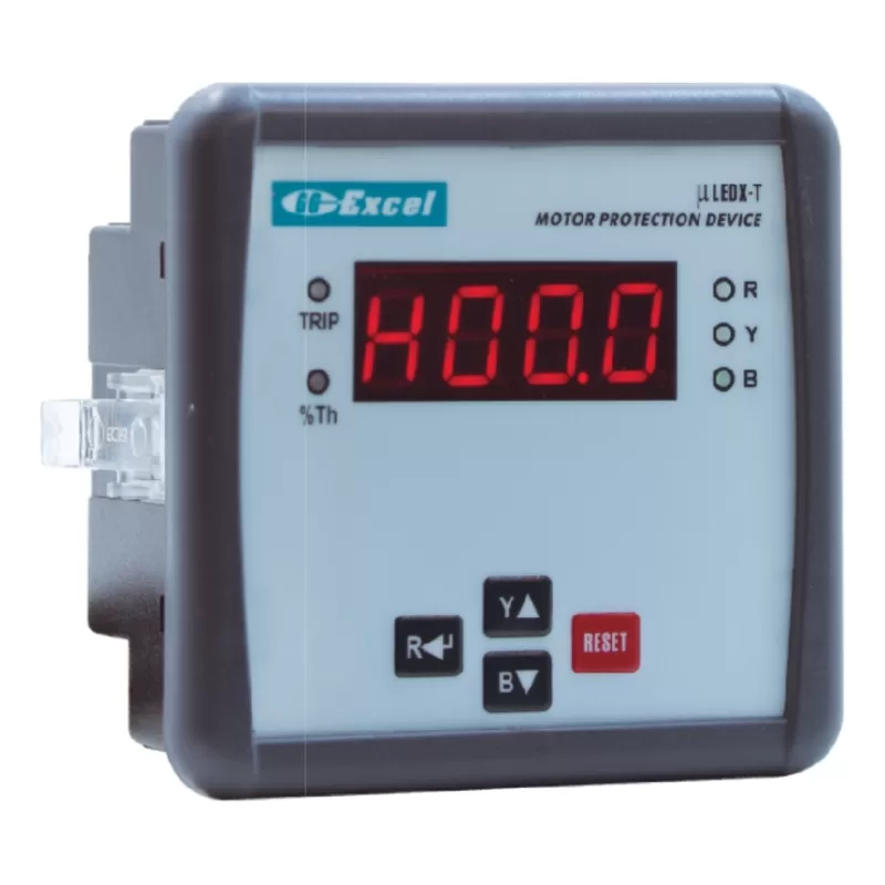
Exceltech µLEDX-T Panel-Mount Motor Protection Relay
- Brand
- Exceltech
- Model number
- µLEDX-T
- Category
- Motor Protection Relays
Microcontroller-based motor protection relay for flush panel mounting, 0.2 A to 500 A with external CTs: overload, single phasing, unbalance, locked rotor, under current, short circuit and earth fault. LED display.
Price and availability on request
Key features
- Microcontroller based, with bright LED seven-segment display
- Numerical algorithm with thermal imaging for fast, reliable operation
- Overload by thermal curve or definite time
- Displays the 3 phase currents and the thermal capacity used
- Annunciation for each type of fault
- Thermal overload curves selectable as required
- Excellent accuracy and long-term stability of the thermal curves (software based)
- Continuous self-supervision and fail-safe operation
- Annunciation if the motor fails to stop after the device issues a trip command
- Keypad for settings
- Up to five trip records (FIFO)
- Reset inhibit function, hour counter, onsite calibration
- Password facility (on demand)
- Robust, shock-proof, non-metallic screwless housing
- 3-phase CTs supplied with the relay, sized to the load
- Options: RS 485 MODBUS RTU, 4 – 20 mA output (or both), relay output for external alarm, external reset, password, phase reversal, thermistor temperature protection, pre-overload alarm
Specifications
| Functions | Overload (thermal or definite time), single phasing (current based), unbalance (current based), locked rotor, under current, short circuit, earth fault (with CBCT) |
|---|---|
| Optional | Phase reversal, thermistor-based temperature protection, pre-overload alarm |
| Rated current (motor FLC) | 0.2 – 500 A in seven CT ranges |
|---|---|
| CT ranges | 0.2 – 6.25 A, 0.4 – 12.5 A, 0.8 – 25 A, 2 – 62.5 A, 4 – 125 A, 40 – 250 A, 80 – 500 A |
| 80 – 500 A range | All protections except short circuit; current measured up to 2000 A |
| CT | External |
| Thermal overload setting range | 0.2 – 500 A, as per the CT range selected |
|---|---|
| Thermal overload curves | 2.5C, 5C, 10C, 15C, 20C and 30C (six curves) or definite time |
| Thermal overload operating time | As per the curve selected, or 1 – 60 s (definite time) |
| Under current | Enable / disable; setting 10% – 80% FLC; operating time 1 – 60 s |
| Locked rotor | Pick-up 3 × FLC; pick-up delay during starting 1 – 30 s |
| Earth fault | Setting 10% – 30% FLC; operating time 0.5 – 3 s; can be blocked for the first 10 s of motor starting |
| Short circuit | Pick-up 8 × FLC; instantaneous (not on the 80 – 500 A range) |
| Single phasing | Enable / disable; operating time 2 s (fixed) |
| Unbalance | Enable / disable; setting 10% – 40%; operating time 3 – 10 s |
| Thermal reset | Enable / disable; reset inhibit time 1 – 999 s (when thermal reset is disabled) |
| Pre-overload alarm (optional) | Alarm point as per the current range selected; time 1 – 60 s |
| Display | LED seven-segment |
|---|---|
| Measures and displays | R, Y and B phase currents, thermal capacity used, hour counter, number of starts |
| Trip records | Up to 5 events (FIFO) |
| Data output | RS 485, MODBUS RTU; 4.8, 9.6 or 19.2 kbps; parity none, odd or even; word length 8 |
|---|---|
| Analog output | 4 – 20 mA DC |
| Auxiliary supply | 85 – 270 V AC, 50 Hz (optional 110 V AC / 415 V AC) |
|---|---|
| Rated frequency | 50 Hz / 60 Hz |
| Mounting | Flush (panel) mounted |
| Dimensions (L × W × D) | 103 × 106 × 52 mm |
| Panel cutout | 92 × 92 mm |
| Weight | Approx. 250 g |
| Ambient temperature | 0 °C – 55 °C |
| Degree of protection | IP54 (front of the device) |
Specifications are from the manufacturer's published information. Confirm critical values with us or the datasheet before ordering.
Related products
-
Enquire about Exceltech WOD
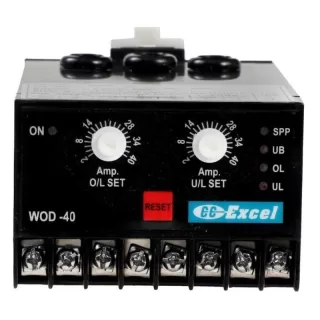
Exceltech WOD Motor Protection Relay with Built-in CT
DIN-rail motor protection relay with built-in CT and LED fault indication: overload (inverse curve), under current, single phasing and unbalance. WOD-5, WOD-20 and WOD-40 for 1 A to 40 A motors.
-
Enquire about Exceltech µDLEDX-T
Exceltech µDLEDX-T DIN-Rail Motor Protection Relay
DIN-rail motor protection relay with LED display, 0.2 A to 500 A (built-in CT up to the 2 – 62.5 A range): overload, single phasing, unbalance, locked rotor, under current, short circuit and earth fault.
-
Enquire about Minilec AUTO SWITCH 2
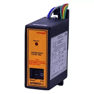
Minilec AUTO SWITCH 2 Auto Switch for Agricultural Pump Starters
Minilec AUTO SWITCH 2 auto switch for agricultural pump starters with 1 NO output, for 200 - 450 VAC, 50 Hz ± 3% supply. Typical uses: agricultural pump DOL starters, pump sets at farms, rivers, and wells, agricultural pump star delta starter.
-
Enquire about Minilec AUTO SWITCH 4
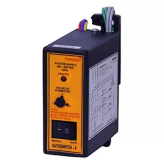
Minilec AUTO SWITCH 4 Auto Switch for Agricultural Pump Starters
Minilec AUTO SWITCH 4 auto switch for agricultural pump starters with 1 NO output, for 200 - 450 VAC, 50 Hz ± 3% supply. Typical uses: agricultural pump DOL starters, pump sets at farms, rivers, and wells, agricultural pump star delta starter.